Stengthening of Cee sections trusses under heavy loads
Trusses are the most efficient form of geometric structure used in construction. Scottsdale pioneers in truss technology with the option to manufacture cold-formed steel trusses out of hat and lipped channel sections. Our intelligent roll formers can manufacture all components of a truss and make connection provisions on the members a breeze through operations such as swage, notch, cut, dimple etc. The state-of-the-art in-house design and engineering software facilitates the design and engineering checks for the roof and floor truss members and corresponding connections in accordance with various country codes of practice.
Cee section trusses from Scottsdale roll formers have been used widely in the low to medium rise building segment by many customers across the globe due to many advantages. These include using the same coil width to roll both wall frames and trusses without the necessity of an additional dedicated truss machine. But the spans achieved by the Cee section trusses are limited in comparison with the Hat section trusses which are dedicated for large truss spans.
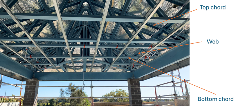
Figure 1 Cee section roof truss
However, there are certain instances where the chord members of the Cee section trusses fail under given loading conditions or when spans are larger. Also, the Scottsdale Cee section trusses are placed in-line (about the minor axis of the section) which is the weakest axis of a Cee section. Inline trusses are oriented this way so that it’s easier to fabricate and also more stable during the manufacturing and shipping process. However, the trade of comes with a reduction in strength where the load demand is high in some projects.
These limitations are often addressed in the design by either of the following
- Decreasing the truss spacing
- Choosing a higher thickness/gauge
- Decreasing the truss span by introducing additional bearing points on the wall
- Increasing the connection capacity by introducing additional fasteners
- Revisiting the assumptions to the loads applied on to the trusses
Despite these mitigation efforts, there can still be instances where the truss top and bottom chord can fail the engineering checks. These failures are often attributed to excessive load demands on these members exceeding the design capacities. This article summarises some methodologies to overcome these design failures and provide optimal solutions for the cold-formed steel truss designers.
Strongback for top and bottom chord members
In general, failure occurs in either the top or bottom chord members of these trusses. Since the Cee section truss chord members are oriented in-line (about the minor axis) the design capacities of these members to withstand higher load demands are less in comparison with the stronger Hat section trusses that Scottsdale offers. To overcome this limitation, a strongback option can be used wherein a new Cee section member oriented about the strong axis (major axis) as shown below can be stitched to both sides of the top and bottom chord of the truss. These strongback members can be produced as linear lengths with the Scottsdale roll formers.
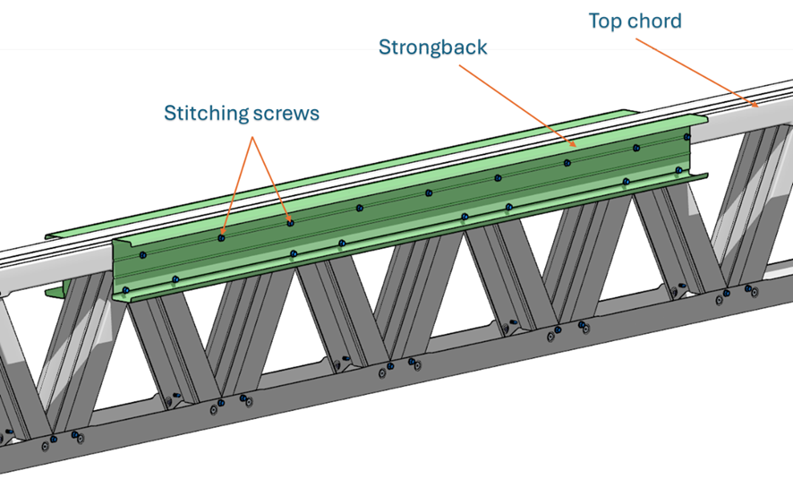
Figure 2 Strongback member stitched to both sides of the top chord
Ideally, the designation of the strongback member can be the same as that of the top and bottom chord. However, based on the project specifications, the strongback member can be either thinner or thicker than the chord members. Likewise, the stitching screws can ideally be spaced at 300 mm c-c for an effective composite action of the strongback member with the existing chord members. The specification of the strongback member along with the fastener spacing must be made in consultation with the project engineer based on the load demand on the member. From an engineering perspective, the section moment capacity of the chord member with the addition of a strongback member increases by over three folds (3x) in comparison with a single inline chord member. Currently the ScotEngineering software does not natively support the strength increase within the engineering. However, this can be computed manually in consultation with the project engineer. The strongback members can be added to existing trusses either within the factory or at site based on project demand.
Table below summarises some typical strengthening details:
| Overstress CSI ratio – Member only | Strongback strengthening | Fixity |
| <1 | Member passes. No strengthening needed | Not applicable |
| >1 to <1.3 | 1 x Strongback member of same thickness along the chord | -1xTek screw at 300 centres along chord -1xTek screw at every brace |
| >1.3 to <1.6 | 2 x Strongback member of same thickness along the chord | -1xTek screw at 300 centres along chord -1xTek screw at every intersecting brace |
| >1.6 | Opt for a stronger section | Opt for a stronger connection |
Double up chords with gusset plates
Similar to the previous option, an alternative way of increasing the strength of the chord members is through doubling up the chord members. In addition to the chord members, the connections can also be strengthened with the addition of gusset plates. Typical details of these connections are shown below.
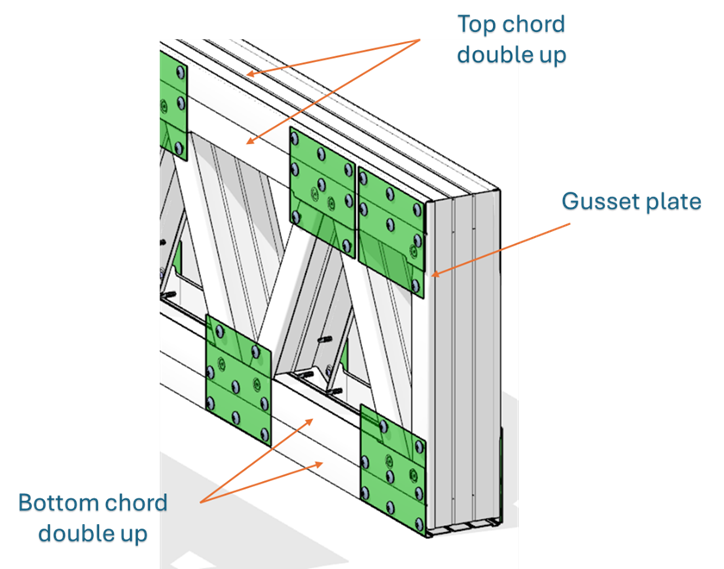
Figure 3 Double up of top and bottom chord members with gusset plate
Unlike a phenomenal jump in the member strength in comparison with the strongback option, the double up of chord member can increase the member strength by up to two folds (2x) with the addition of the gusset plates. The reduced strength increase is because of the orientation of the double up member about the weaker axis as explained previously. Gusset plates are required at every connection brace as shown in the image to achieve a composite action amongst the double up chord members. This option is suitable for projects where the load demand is not too high and a cleaner finish is desired. Double up of the chord members can be achieved by designing it within the ScotSteel design package and manufactured using the Scottsdale roll formers with the necessary connection holes at the appropriate location within the factory. This reduces mishaps on site and less error as the members are sent for rolling to the roll formers sequentially by the intelligent ScotRF software.
ScotEngineering does not inherently support the strength increase of the double up option with the automated truss engineering process. However, this option can be specified by an engineer or a designer during the design process.
Table below summarises some typical strengthening details:
|
Overstress CSI ratio – Member only |
Double up strengthening |
Fixity |
|
<1 |
Member passes. No strengthening needed |
Not applicable |
|
>1 to <1.25 |
1 x Double up member of same thickness along the chord |
-Gusset plate of same member thinckness or more |
|
>1.25 |
Opt for a stronger section |
Opt for a stronger connection |
Contact us
We don’t only design and sell roll forming machines.
We also provide comprehensive global solutions to meet the needs of our customers anywhere. From powerful software design (ScotSteel, ScotRF) to 24/7 customer support service, material supply, and financial solutions.
We offer everything you need to run your business successfully—all in one place.
With over 16,000 roll forming machines supplied globally, 4,600 clients across 100 countries, 105 patents garnered for groundbreaking technology, and over 50 innovative products for residential and commercial construction, we are determined to support you throughout the entire process to ensure your business grows.
Feel free to reach out to us for utilising these truss strengthening options within your project to get the maximum benefit out of the Cee section trusses. Please contact us at sales@scottsdalesteelframes.com or call one of our experts at +1 (888) 406-2080 or + 61-1300 671 345.

