Steel frame houses are gaining popularity worldwide because they offer significant advantages, such as a high strength-to-weight ratio, non-combustibility, faster construction times, improved quality control, and superior finishes. As a result, more builders are shifting away from traditional timber-framed construction, which not only enhances sustainability but also promotes the use of recyclable materials like steel. Nevertheless, designing a steel frame house introduces several engineering and design challenges that must be carefully addressed. Therefore, this article highlights the key obstacles engineers face when working with steel frame houses and, furthermore, serves as a comprehensive guide to help practicing engineers design cold-formed steel frame house structures more efficiently.
Jump to Section
- Steel Frame House Architectural Plans
- Load Flow Path in Steel Frame Homes
- Preliminary Member Designation in Steel Frame House
- Structural Analysis and Engineering Design for Steel Frame House
- Documentation and Certification for Steel Frame House
- Using Scottsdale Software Suite for My Next Steel Frame House Project
Steel Frame House Architectural Plans
The first step in designing a steel-framed house involves gathering the approved architectural plans and carefully assessing the feasibility of maximizing the use of light-gauge steel frames in the project. To achieve this, engineers must actively collaborate with architects, clients, and steel frame manufacturers to finalize the architectural plans while ensuring minimal reliance on hot-rolled steel. Consequently, this approach not only enhances productivity but also significantly reduces costs during construction. Moreover, early collaboration among the entire project team allows for better optimization of material usage and greater structural design efficiency, all while ensuring that the client’s requirements are fully met.
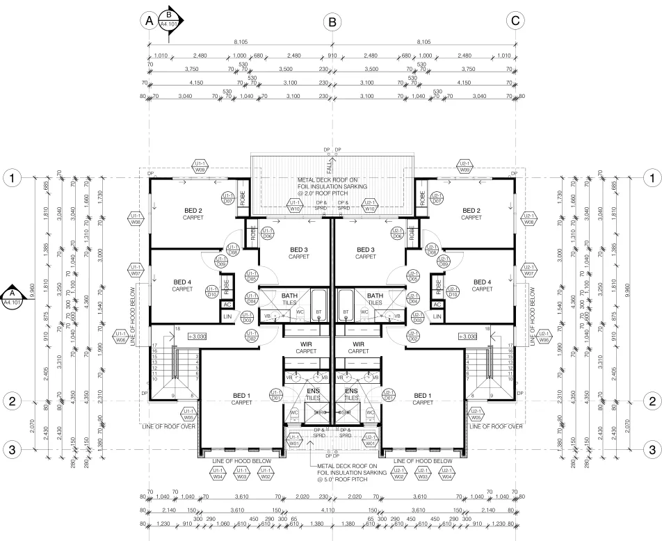
The image below, for instance, illustrates a typical architectural plan for a townhouse.
Load Flow Path in Steel Frame Homes
Once the architectural plans are finalized, the next step is to determine the load flow path in the steel framing system. Specifically, this involves identifying the type of steel framing system used in the project. Steel frame manufacturers commonly use steel frames and trusses for houses. Additionally, other options include steel-framed joists and rafters for roofs and floors. Furthermore, wall systems typically use studs, noggings, and top and bottom plates, which are similar across manufacturers.
After selecting the manufacturer based on client and builder preferences, the next step is to calculate the loads acting on the steel frame house and establish a clear path to transfer these loads from the roof to the foundation.
Moreover, loads such as live, wind, seismic, and snow loads are determined by country-specific codes and standards. At the same time, dead loads depend on the materials chosen during the architectural planning stage. Therefore, the design engineer must carefully consider all these loads and account for the service and ultimate limit states the steel frame house may experience over its lifetime.
Ultimately, calculating the loads and defining the load path ensures no critical factors are overlooked during the design and construction of the steel frame house. This process guarantees the safety of the occupants throughout the building’s service life.
The image below shows a typical load flow path in a steel frame house.

Preliminary Member Designation in Steel Frame House
The most critical step in the structural design process is selecting the appropriate members and their sizes for key components such as walls, roofs, floors, and ceilings. To do this effectively, the design engineer must first understand the types of sections the steel frame manufacturer provides for each part of the building. Furthermore, engineers should prioritize specifying standard members from the product catalog. By doing so, they can prevent disruptions in procurement and supply, thereby ensuring a smoother construction process.
However, in some cases, architectural plans may require wider spans or larger loaded widths for specific building elements. When this occurs, engineers can explore alternative solutions, such as proposing composite cold-formed sections instead of hot-rolled steel sections. Not only can this approach reduce material and erection costs, but it can also optimize overall structural efficiency. Nevertheless, there are situations where hot-rolled sections may still be necessary. For instance, areas like garage openings or wide-span hallways, particularly in double-story houses often require hot-rolled sections to provide adequate support for the cold-formed steel floor system
Structural Analysis and Engineering Design for Steel Frame House
Once the design engineer selects preliminary sizes, the next step is to analyze and confirm their adequacy, ensuring they meet the required standards. This step is crucial for maintaining structural integrity and compliance.
Unlike hot-rolled steel structures that rely on external analysis tools, cold-formed steel design software from manufacturers simplifies the process. Specifically, it converts architectural plans into fabrication models while simultaneously performing engineering checks. As a result, this approach enhances efficiency, reduces errors, and accelerates project timelines.
Sometimes, software packages can only detail the steel frame house based on architectural plans and generate shop drawings. When this happens, the design engineer must turn to external software for structural analysis and design checks. Consequently, this process involves several key steps:
- First, generating engineering geometry for light-gauge steel frames and applying appropriate boundary conditions.
- Next, resolving loads and distributing them to members such as cold-formed steel trusses and panels.
- Then, performing static structural analysis (linear or non-linear) to determine forces on cold-formed steel members.
- After that, checking member designs against the relevant country code of practice to ensure load demands from the analysis are met.
- Finally, designing and verifying bracing and connections for structural stability.
While structural engineering software like STAAD.Pro, Space Gass, and ETABS can handle analysis and design, they often require significant manual effort and time. Therefore, tools like ScotSteel and ScotStruct provide a more efficient alternative, streamlining these tasks and reducing workload.
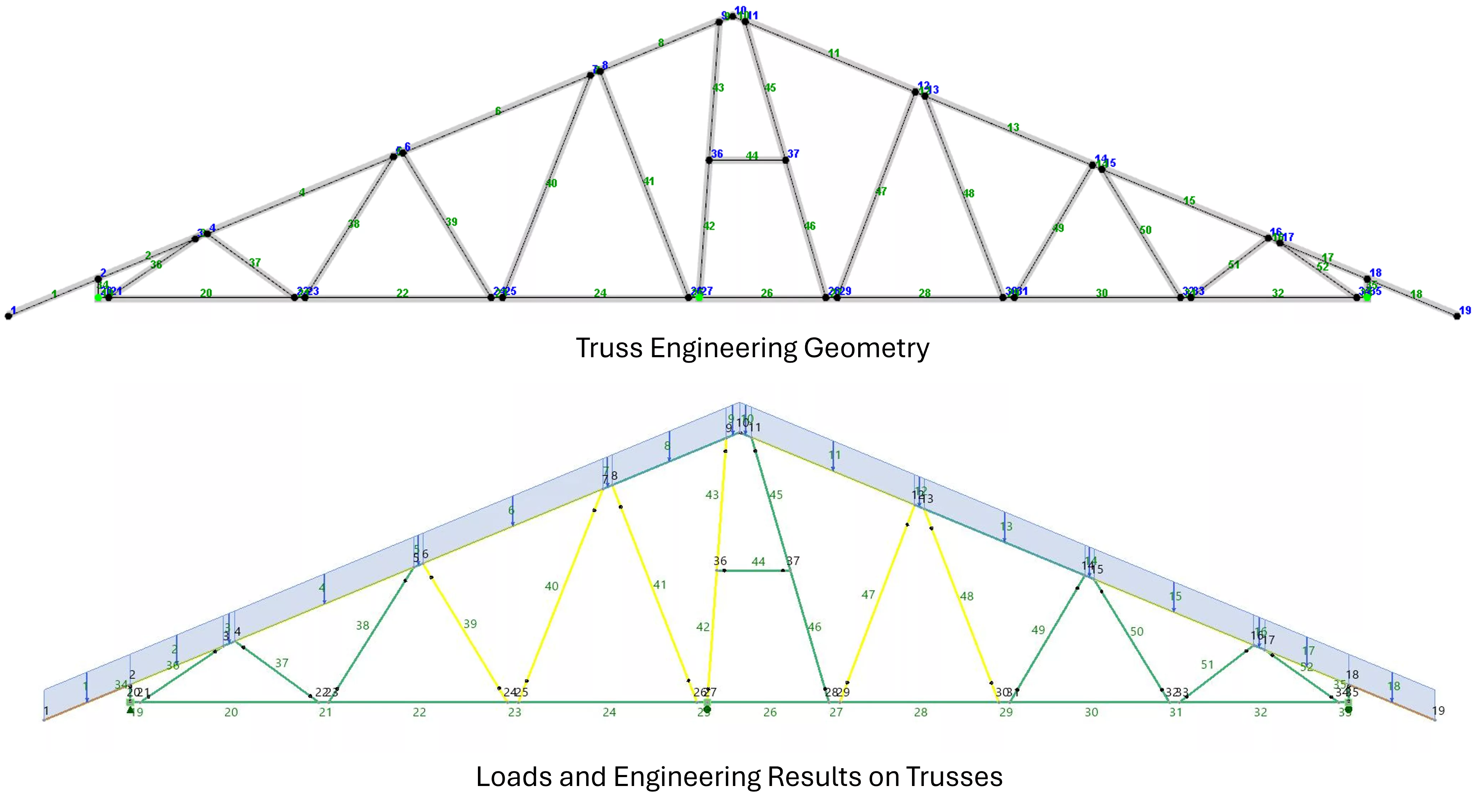
The images below, illustrates automated engineering geometry and results within ScotSteel truss engineering.
Documentation and Certification for Steel Frame House
Documents and certificates are essential for obtaining approval from local government bodies. They also help builders construct the steel frame house efficiently, avoiding additional costs. After the design stage, the engineer approves the member designations and prepare detailed layouts and calculations report. These documents serve multiple stakeholders in the project and typically include the following:
- A typical layout from the architectural plan, showing member designations for all elements along with a legend.
- Any non-standard member designations and their specifications that differ from typical details.
- Typical connection designs for all elements used in the steel frame house.
- A quantity takeoff and bill of materials to help the estimation or quantity surveying team calculate precise costs and track project progress.
- Detailed design calculations as separate reports for review by third parties and certifying authorities.
- Design certification, which forms the basis for construction and approval.
- Inspection certification at various stages during construction.
The documentation process remains consistent globally, regardless of location or standards. However, the sequence of steps and specific documentation may vary slightly based on regional rules and standards.
Using Scottsdale Software Suite for My Next Steel Frame House Project
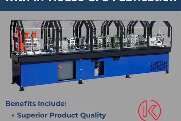
Scottsdale Construction Systems offers custom design and engineering software packages to support your next steel frame house project. We develop all our software in-house from scratch, ensuring seamless compatibility with our roll-forming machines. Our solutions provide end-to-end support for all your light-gauge steel framing needs. Below is a list of our cutting-edge design and engineering software options.


ScotSteel is a bespoke 3D software that facilitates the design and engineering of cold-formed steel sections within the Scottsdale ecosystem. It boasts advanced tools for rapid drafting and engineering of cold-formed steel structures with ease. The built-in import tools make it seamless to trace framing drawings from architectural plans, while the export tools help with precise quantity take-offs.
ScotStruct is a powerful engineering tool that performs structural analysis and design of cold-formed steel using the Direct Strength Method (DSM). With modules for walls, bracing, lintels, and more, it easily integrates project data from ScotSteel to handle complex cold-formed steel projects, ensuring accuracy and compliance with modern engineering standards.
ScotRF is a comprehensive roll forming and production management software that works seamlessly with ScotSteel. It includes modules for trusses and panels, enabling the production of Hat and Cee section profiles. Designs created in ScotSteel are directly communicated to ScotRF, which controls the roll formers for efficient and precise production of cold-formed steel components.
If you plan to establish the next steel frame house manufacturing hub in your area, our expert team is ready to assist. Contact us at sales@scottsdalesteelframes.com, call +1 (888) 406-2080 (Option 1), or dial +61 1300 671 345. We specialize in guiding you through every step of setting up a state-of-the-art cold-formed steel manufacturing facility. Our goal is to ensure a seamless and efficient process. Let us help you build a successful and sustainable operation.